Future of Reverse Engineering
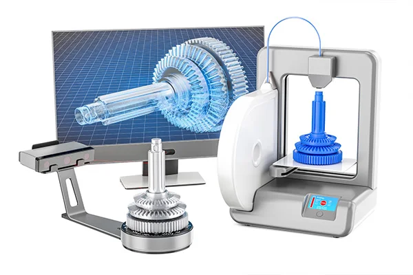
Reverse engineering found its use in various industries gradually, as more and more industry leaders adopted this approach and implemented the same, thereby easing out their own work-process. Here is a list of industries that use reverse engineering as a part of their methods: The future It is the 21st century. These are great times for design engineers. Over the past two decades, their job has been dramatically changed, with the transformation of finite element analysis (FEA) software from mainframe to desktop computer. With the easy availability of computer-aided design software packages, reverse engineering technology has become a practical means to create a 3D virtual model of an existing physical part. That, in turn, has made the use of 3D CAD, CAM, or other CAE applications easier. The convenience in the usage, affordability and the ability of its software to tightly integrate with a CAD program has made this process a much favored among engineers. At the same time, the costs of scanners and other hardware used to input measurements have been dropping, and the hardware is becoming smaller and easier to use, according to the hardware makers.
Read More
Reverse Engineering Inspection and its use
The quality control and inspection process in reverse engineering usually take three steps to determine if the 3D CAD model of the part is available or not. Those three steps are as follows: Following are some uses of Reverse engineering inspection:
Read More
What are Parametric and Non-parametric Modeling
Table of content Parametric Model/Modeling Non-parametric Model/Modeling In the past, designers resorted to the physical measurement of the product to redraw its geometry. Today, designers use 3D scanners to capture measurements. The scanned data is then imported to CAD, where the design can be analyzed, processed, manipulated, and refined. Two key aspects that fall in place when focusing on the reverse engineering process are: Parametric Model/Modeling A parametric model captures all its information about the data within its parameters. All you need to know to predict a future data value from the model’s current state is its parameters. The parameters are usually finite in dimensions. Knowing the parameters for a parametric model to predict new data is enough. A parametric model is one where we assume the ‘shape’ of the data and, therefore, only have to estimate the coefficients of the model. A significant advantage of parametric modeling is that it compactly describes the underlying process, making further data processing more accessible. However, most work in parametric system identification relies on the assumption of time-invariance of the system and stationarity of the observed signal. But this assumption is not valid for all signals. In these cases, a heuristic approach often determines the optimal reduced model. Parametric models keep a history of the parameters that determine a model’s geometry. As a result, they allow the user to explore different design options while minimizing edit time. Similarly, parametric models can be visualized in 3D drawing programs. It means that they can more closely simulate the actual behavior of the original project. Non-parametric Model/Modeling A non-parametric model can capture more subtle aspects of the data. It allows more information to pass from the current set of data attached to the model at the current state to predict future data. The parameters are usually said to be infinite in dimensions. Hence, it can express the characteristics in the data much better than parametric models. For a non-parametric model, predicting future data is based not just on the parameters but also on the observed data state. A non-parametric model is one where we do not assume the ‘shape’ of the data, and we have to estimate the most suitable form of the model, along with the coefficients. Parametric models require a fixed number of parameters, while non-parametric ones don’t. The former is better for models with well-defined and predictable input data. Non-parametric models can be trained with a more significant number of data. However, the disadvantages of a parametric model are greater training time. While both models effectively predict the future, the latter tends to produce better results. The former requires less training data but is faster than non-parametric methods. Non-parametric models have the disadvantage of overfitting because they need many observations to approximate f. Non-parametric models have a much lower precision rate but can produce better-fitting models. As for the disadvantages of both models, parametric models are generally easier to understand and use. Besides requiring less training data, parametric models tend to produce poorer results. It is why they are more popular. However, the benefits of non-parametric algorithms are far outweighed by their disadvantages. The latter is often better for data that are not linear or have many missing values. Parametric models use different methods to estimate model parameters. Parametric modeling is based on mathematical functions, while non-parametric models are based on data. The difference between the two is a big one and can make the difference between success and failure in the field of statistics.
Read More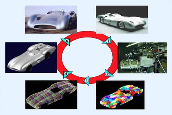
The Reverse Engineering process
Sometimes, situations arise where you don’t have access to a part’s original design documentation from its original production. This might be due to the absence of the original manufacturer altogether or stoppage on the production itself. Reverse engineering empowers us to analyze a physical part and explore how it was originally built to replicate, create variations, or improve on the design. The goal is to ultimately create a new CAD model for use in manufacturing. Let us take a look at the steps involved in reverse engineering. Commonly, it involves careful executions of the following steps: Scanning The first step involves using a 3D scanner for collecting the geometric measurements and dimensions of the existing part quickly and accurately using projected light patterns and camera system. Generally, the types of scanners used for such execution are blue light scanner, white light scanner, CT scanner and /or laser scanner. The former two captures the outward dimension and measurements while the latter two is capable of scanning the entire inside out. Point Cloud Once a certain part is scanned, the data gets transformed in the form of point clouds. Point cloud is a 3D visualization consisting of thousands or even millions of points. Point clouds define the shape of a physical system. Meshing/Triangulation This stage serves involves conversion of point clouds to mesh (STL or Stereolithographic format). Mesh generation is the practice of converting the given set of points into a consistent polygonal model that generates vertices, edges and faces that only meet at shared edges. Common software tools used to merge point clouds are Polywords, Geomatics, Image Ware, MeshLab. The meshed part is then run for alignment in the mentioned software tools. Parametric/Non-parametric Modeling After the meshed part is aligned, it goes through either of two stages. The first option involves applying surface modeling on meshed part in tools such as Polyworks. It results in the generation of non-parametric model (IGES or STEP format). An alternate option is creating a sketch of the meshed part instead of putting it through surfacing. This work-process is known as parametric modeling (.PRT format). For a non parametric model, predicting future data is based on not just the parameters but also in the current state of data that has been observed. For a parametric model to predict new data, knowing just the parameters is enough. CAD Modeling The next stage consists of transferring the data through CAD software tools such as NX, Catia, Solidworks, Cero etc., for applying functions such as ‘stitch’, ‘sew’, ‘knit’, ‘trim’, ‘extrude’, ‘revolve’ etc for creation of 3D CAD model. Inspection This stage includes visual computer model inspections and alignment of the merged models against actual scanned parts (STL) for any discrepancies in the geometry as well as dimensions. Generally, inspection is carried out by using tools such as Polyworks or Geomagic. Reverse engineering inspection provides sufficient information to check tolerances, dimensions and other information relevant to the project. Documentation Documentation of 3D stage model depends solely on one’s technical/business requirements. This step is about converting 3D model to 2D sketch, usually with the help of tools such as inventor or Isidra/Coral draw, citing measurements which can be used for reference in the future.
Read More
What is Reverse Engineering ?
Let us start with an example. One day you get into your garage and find on the workbench a ‘black box’. Stricken by curiosity, you build up an urge to discover what it ‘is’ and what it ‘does’. You start with an inspection of the box’s dimensions, color. Then you try to find its purpose and then how it operates. Not satisfied, you try to open it, break it apart, piece by piece in an attempt to understand what each component does and build up a pattern of how they would all interact together as one system. Finally you reach the end of your inquisition. You now fully (or partially) understand the box. This very approach is termed as Reverse Engineering.Reverse engineering, also known as back engineering, is the process where a man-made object is dismantled completely to reveal its architecture, design or to extract knowledge from the object about its functioning and structural integrity. Why do you need Reverse Engineering? There might be innumerable reasons to adopt reverse engineering process. Some of the common cases are as follows:
Read More
Reverse Engineering vocabulary
3D Scanning – The process of collecting 3-Dimensional data from physical object through a variety of data acquisitions devices. 3D to CAD: The process of converting 3-Dimensional point to a dimensionally defined graphic model. Accuracy: The extent of how close a measurement is to the recognized true value. Annotation Models: A digital model containing specific coordinate locations verifying deviations from nominal data. AS IS CAD: A CAD model that represents actual manufactured parts rather than a designed CAD model. CAD (Computer-aided design): The use of computer technology to assist in the creation, analysis, or modification of a design. CAM (Computer Aided Manufacturing): The use software that can support both machine tools and 3D CAD modeling capabilities. Cone beam: A conical-shaped x-ray beam that produces two dimensional images of an object. Design intent: The process of taking a manufactured part into account with inherent errors and modifying the same till it is true. GD&T (Geometric Dimensioning and Tolerancing): System of languages and symbols used for defining and communicating engineering tolerances. Hand held scanner: Portable camera that is used for capturing 3D imagery of objects with a laser or structured light based. Hybrid Model: Combining two different modeling processes to accurately define 3D geometry. Laser Scanner: A device used to capture 3D surface geometry, consisting of a laser output and a sensor to interpret the data. LIDAR: A combination of the words: “Light” and “RADAR.” A LIDAR scanner employs RADAR’s technique of emitting a signal and measuring distances to objects based off of the signals reflection. Long Range Scanning: Acquiring data at expansive distances from hundreds of feet away to miles away. Data can be captured through a variety of devices including LIDAR, Time of Flight and phase shift scanners. Modeling: Digitally creating 2D or 3D object using CAD or data manipulation software, such as Polyworks, Geomatics or Solid works. NanoCT: Capturing images using CT (Computed Tomography), with a resolution of the images defined in nanometers. Parametric Model: A sketch driven model that builds a design tree that can be opened in a CAD environment and allows the operator to manipulate the model. Parametric Modeling: This process is taking 3d scan data and through the use of design tools, creating a sketch driven model with consistent relationships between features in the feature tree. Phase Based Scanners: LIDAR Scanners that take measurements by sending laser pulses towards an object and measuring the phase shift of the pulses’ reflection off of the object. Point Cloud: A set of points defined by X, Y, and Z coordinates that represent the external surfaces of an object. Prismatic Modeling: Creating CAD geometry using basic geometry shapes, i.e. planes, cylinders, cones etc, to define correct shapes of the 3D geometry. Re-Engineering: The process of modifying an existing part or assembly of parts digitally to improve its performance or use. Repeatability: The variation in measurements taken with the same piece of equipment, under the same conditions, across multiple tests. Reverse Engineering: The process by which a man-made object is dismantled to reveal its architecture, designs, or to extract knowledge from the object in order to know about its functioning and structural integrity. SCAN to CAD: The process of collecting 3D data using 3D scanning hardware and converting the dimensional data to CAD format using a variety of software packages. 2D Drawings / Schematics: A 2D print that describes the physical characteristics of an object, how it should be made, assembled, handled, etc. These can be used to provide basic dimensional values to define its function. Sectioning: The process of creating 2D profiles through sections of an object. Short range scanning: A process used to collect dimensional data in 3D space from short ranges. Solid Modeling: Defining an object with CAD tools such as extrudes, revolves, sweeps, etc. A solid model is enclosed and is said to have mass and volumetric values can be calculated. Surface Model: An objects exterior skin defined by CAD features or NURBS surfaces. Triangulation Scanner: Projecting a known pattern of light grids or fringe onto an object in order to calculate surface geometry by analyzing the distortions of the pattern. White Light Scanner: A 3D camera projecting a known pattern of light grids or fringe onto an object in order to calculate
Read More