
The design model is a depiction of a part design. However, the design model can never be an accurate representation of the product itself. Due to shortcomings in manufacturing and inspection processes, physical parts never match the design model exactly. An essential aspect of a design is to specify the lengths the part features may deviate from their theoretically accurate geometry. It is vital that the design intent and functionality of the part be communicated between the design engineers and the manufacturing unit. It is where the approach of GD&T comes into play.
Geometric dimensioning and tolerancing or GD&T is a language of symbols and standards used on engineering drawings and models to determine the allowable deviation of feature geometry.
GD&T consists of dimensions, tolerances, definitions, symbols, and rules that enable the design engineers to convey the design models appropriately. The manufacturing unit uses the language to understand the design intent.
To master GD&T, one needs to understand the crucial concepts, which includes:
- Machining tolerances: Tolerances mean the allowable amount of deviation from the proposed drawing. Machined parts look flat and straight through the naked eye, but if viewed with calipers, one can find imperfections all over. These imperfections or variations are allowed within the tolerance constraints placed on the parts. Tolerances should be kept as large while preserving the functions of the part.
- The Datum Reference Frame: DRF is the most important aspect of GD&T. It is a three-dimensional cartesian coordinate system. It’s a skeletal reference to which all referenced geometric specifications are related.
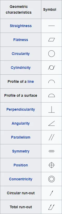
- GD&T Symbols: It is essential to be familiar with numerous symbols and types of applied tolerance in GD&T. The language of symbols makes it easier to interpret designs and improve communications from the designer to the shop. By using GD&T standard, the design intent is fully understood by suppliers all over the world.
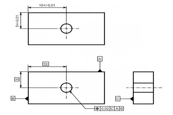
- Feature Control Frame: The feature control frame describes the requirements or instructions for the feature to which it is attached. A feature control frame contains only one message. If a feature needs two messages, the feature would need the corresponding amount of feature control frames for every message required.
- Basic Dimensions: Basic dimensions are exact numerical values in theory, which defines the size, orientation, form, or location of a part or feature.
- Material Condition Modifiers: It is often necessary to state that a tolerance applies to a feature at a particular feature size. The Maximum Material Condition (MMC) allows an engineer to communicate that intent.
GD&T is an efficient way to describe the dimensions and tolerances compared to traditional approximation tolerancing. The engineer might design a part with perfect geometry in CAD, but the produced part, more often than not, turns out to be not accurate. Proper use of GD&T improves quality and reduce time and cost of delivery by providing a common language for expressing design intent.