
The art of metalworking has a primary concern, locating the part to be machined relative to the platform. A CNC machine starts machining at a specific point corresponding to the fixture and proceeds from there. Therefore, the preciseness with which a job is machined is dependent on the accuracy that holds in the fixture. The accurate location of every part loaded into the fixture is essential. Any deviation in part location adds to the dimensional tolerance that must be assigned to the finished pieces. Furthermore, improper supporting and securing the part in the fixture affects surface finishes by temporarily or permanently deforming it. Hence, techniques for supporting, clamping, and locating must be considered together to assure repeatability from part to part.
Basic principles of Jigs and Fixtures design
LOCATING POINTS: Locating the work is a prime necessity and requires suitable facilities. The correct setup ensures smooth insertion of a workpiece in the proper position and removing a workpiece from a jig without operational hassles or time consumption. The workpiece position needs to be precise with the guiding tool in the jig or setup pieces in the fixture.
FOOLPROOF: A foolproof design of jigs and fixtures does not permit a tool or workpiece to be placed in any other way other than the intended one.
REDUCTION OF IDLE TIME: Jigs and Fixtures must be designed in such a way that ensures smooth loading, clamping, machining, and unloading of a
WEIGHT OF JIGS AND FIXTURES: A jig and fixture must be compact, easy to handle, and low cost regarding the number of materials used without giving up stiffness and rigidity.
JIGS PROVIDED WITH FEET: Some jigs require feet so that they can be placed on the table firmly.
MATERIALS FOR JIGS AND FIXTURES: Jigs and Fixtures are usually created with hardened materials to resist wear & tear and avoid frequent damage—for example, Mild steel, Cast iron, Die steel, High-speed steel, Caesium.
CLAMPING DEVICE: A suitable clamp is rated for its strength. It should be able to hold a workpiece firmly in its position while bearing the strain of the cutting tool simultaneously, without springing.
Broad rules of Jigs & Fixtures Design
- Compare the production cost of work between the existing tools and the tool to be made and see if the manufacturing price is not more than the expected gain.
- Determine location points and outline clamping arrangement.
- Make sure the clamping and binding pieces are as quick to act & efficient as possible.
- Make the jig and fixture foolproof.
- Make sure the locating points are adjustable.
- Do avoid intricate clamping arrangements.
- Round all corners.
- Make sure the operator has handles to make handling tasks easier.
- Provide ample amount of clearance.
- Provide holes for chips to escape.
- Systematically locate clamps to resist the pressure of the cutting tool while machining.
- To avoid springing action, place all clamps in proximity opposite to the bearing point of the workpiece.
- Test the jigs before putting them in a shop.
The 3-2-1 principle
Locating a part to be machined involves mainly three steps: Supporting, Positioning, and Clamping.
Two main intentions when placing a job on a jig/fixture are:
- Precisely positioning the part at the desired coordinates.
- Curbing all six degrees of movement so that the part cannot budge.
An extensively used method for obtaining these objectives is the 3-2-1 principle or six degrees of freedom for part location.
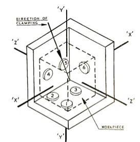
The 3-2-1 method is a work-holding principle where three pins are located on the 1st principle plane, i.e., either XY, YZ, ZX. And two pins are located on the 2nd plane perpendicular to the 1st plane, and at last, one pin on the plane is mutually perpendicular to the 1st and 2nd planes. The aim is to constrain the movement of the workpiece along all three axes.
Design objectives of Jigs and Fixtures
Before sitting down to design jigs/fixtures, the designer must consider the following points:
- The tool must be foolproof to prevent any mishandling or accidental usage by the operator.
- Easy to operate for increasing efficiency.
- Easy to manufacture using the lowest costs.
- Its ability to weather the tool life instead of appropriate materials.
- Must be consistent at producing high-quality parts.
- Must be safe and secure to use.
The designer must know the basics of the process and the tools associated with it for which the jig/fixture is designed. Overall objectives to look out for a while developing such tools are:
- Cycle time.
- Type of Jig/Fixture.
- Part Assembly sequence or Machining locations.
- Joining or machining process.
- Clamping method and clamping sequence.
- Required output accuracy.
- Type of equipment to be used with the jig.
- Method of ejecting finished output and transferring it to the next. Platform, whether the manual or automatic mode.
- The type of material, recommended weight, number of spots involving welding.
Reference: National Institute of Technology, Calicut