
Sometimes, situations arise where you don’t have access to a part’s original design documentation from its original production. This might be due to the absence of the original manufacturer altogether or stoppage on the production itself.
Reverse engineering empowers us to analyze a physical part and explore how it was originally built to replicate, create variations, or improve on the design. The goal is to ultimately create a new CAD model for use in manufacturing.
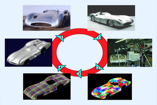
Let us take a look at the steps involved in reverse engineering. Commonly, it involves careful executions of the following steps:
Scanning
The first step involves using a 3D scanner for collecting the geometric measurements and dimensions of the existing part quickly and accurately using projected light patterns and camera system. Generally, the types of scanners used for such execution are blue light scanner, white light scanner, CT scanner and /or laser scanner. The former two captures the outward dimension and measurements while the latter two is capable of scanning the entire inside out.
Point Cloud
Once a certain part is scanned, the data gets transformed in the form of point clouds. Point cloud is a 3D visualization consisting of thousands or even millions of points. Point clouds define the shape of a physical system.
Meshing/Triangulation
This stage serves involves conversion of point clouds to mesh (STL or Stereolithographic format). Mesh generation is the practice of converting the given set of points into a consistent polygonal model that generates vertices, edges and faces that only meet at shared edges. Common software tools used to merge point clouds are Polywords, Geomatics, Image Ware, MeshLab. The meshed part is then run for alignment in the mentioned software tools.
Parametric/Non-parametric Modeling
After the meshed part is aligned, it goes through either of two stages. The first option involves applying surface modeling on meshed part in tools such as Polyworks. It results in the generation of non-parametric model (IGES or STEP format). An alternate option is creating a sketch of the meshed part instead of putting it through surfacing. This work-process is known as parametric modeling (.PRT format). For a non parametric model, predicting future data is based on not just the parameters but also in the current state of data that has been observed. For a parametric model to predict new data, knowing just the parameters is enough.
CAD Modeling
The next stage consists of transferring the data through CAD software tools such as NX, Catia, Solidworks, Cero etc., for applying functions such as ‘stitch’, ‘sew’, ‘knit’, ‘trim’, ‘extrude’, ‘revolve’ etc for creation of 3D CAD model.
Inspection
This stage includes visual computer model inspections and alignment of the merged models against actual scanned parts (STL) for any discrepancies in the geometry as well as dimensions. Generally, inspection is carried out by using tools such as Polyworks or Geomagic. Reverse engineering inspection provides sufficient information to check tolerances, dimensions and other information relevant to the project.
Documentation
Documentation of 3D stage model depends solely on one’s technical/business requirements. This step is about converting 3D model to 2D sketch, usually with the help of tools such as inventor or Isidra/Coral draw, citing measurements which can be used for reference in the future.